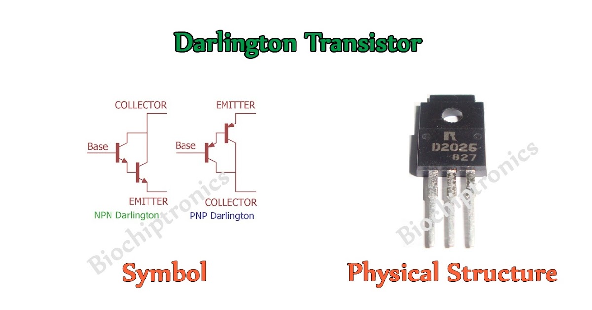

Text: Collector-Emitter Saturation Voltage Industrial Use 1 TO- 220 2.Collector 3.Emitter 1.Base NPN Epitaxial, Rev. Text: ) for switching regulators 2N6385 Darlington FAMILY (silicon) Gain Bandwith = 20 MHz min f =, 2N6388 Darlington FAMILY (silicon) Gain Bandwith = 20 MHz min = 1 MHz Pj = 40 W max 2N6386 Darlington, TO- 220 AB 40 40 40 1000 min. Text: TIP145T/146T/147T 1 TO- 220 2.Collector 3.Emitter 1.Base NPN Epitaxial Silicon Darlington, - NPN Epitaxial Silicon Darlington Transistor SEARCH | Parametric | Cross Reference space, space space TIP141T Products groups NPN Epitaxial Silicon Darlington Transistor Analog and Mixed Signal, Product Folder - Fairchild P/N TIP141T - NPN Epitaxial Silicon Darlington Transistor space space, Fairchild P/N TIP142T - NPN Epitaxial Silicon Darlington Transistor SEARCH | Parametric | Cross Reference
#Darlington transistor application code
But the whether they are needed or not depends on the application.Darlington npn to-220 Datasheets Context Search Catalog DatasheetĪbstract: equivalent 2SC2655 2sc5858 2sC5200, 2SA1943 2sa1930 transistor equivalent 2SA1941 equivalent 2sc5570 zener diode SMD marking code 27 4F 2sc5200 audio amplifiers smd transistor h2a

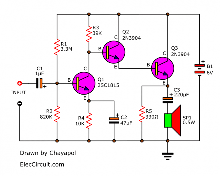
This 15mA flows into the base of the second transistor where it is again amplified and into the second transistors collector you get 1530=450mA.īy using this configuration for all of the loads you have cut down the amount of current the microcontroller has to source from 300mA down to 20mA, which is much better for the microcontroller.īasically the darlington pair (or triple, or quadruple etc) allow you to get higher gains in current than a single transistor. This gets amplified so that 0.5 30=15mA flows into the collector and out of the emitter from the power supply. In this configuration lets say you put 0.5mA into the base of the first transistor. The second transistor is used to drive the load. Its collector is connected to Vcc, and its emitter is connected to the base of a second transistor. The base of the first is connected to the the arduino via a resistor to control the base current. Instead what if you used two transistors for each load. That would require you to source ~17mA form every pin which would go far beyond the maximum power dissipation of the chip. The arduino can source 20mA which means for this gain you can have a maximum collector current of around 600mA.īut what if you need to drive say 20 x 0.45A loads individually. This is fine for smallish control signals such as that from an arduino pin. What this means is that for every 1mA that flows into the base, 30mA can flow into the collector. Though this is somewhat meaningless without any specific part.Īn example - you haven't given any information on purpose, so I will make up a unrealistic example to demonstrate.įor a BJT (Bipolar Junction Transistor), the current that flows into the collector is proportional to the current that flows into the base.įor example transistor x has a Beta, or current gain, of around 30.

Multiple transistor stages means more noise, and possibly a slower response.


 0 kommentar(er)
